Equipment Used By The Artillery Regiments
During the war only a few difference artillery pieces were deployed, but they all had many variations to make them more suitable to the theatre of action. The most development was in the area of the anti-tank gun in order to gun to counter the heavier and more powerful German tanks, such as the Panther and the Tiger. What follows is a brief summary of the Ordnance used by the various Artillery Regiments that served in the Division during the Second World War
Artillery Ordnance
The artillery piece was basically the same as was used during the First World War, but with some modifications, such as pneumatic tyres and split-trail design to allow it to be towed behind a tractor unit, such a lorry or the Quad tractor and limber.
The gun fired a high velocity round on a relatively flat trajectory, which although was suitable for many tasks, it was not well suited to lobbing explosive shells over intervening obstacles, for which a Howitzer was developed. The was first produced in 1904, along with the smaller 13-pdr Field Gun, saw extensive service during the First World War and was the backbone of divisional artillery units between the wars, until it started to be replaced in 1938. It saw service until the latter stages of the Second World War albeit in a training or reserve capacity. It is worth noting that its slightly smaller companion the 13 pdr is still in service with the King's Troop Royal Horse Artillery to this day, in their ceremonial role!
18-pdr MK-4, Data:
|
Calibre (mm/in) |
Shell Weight (Kg/lb.) |
Max Velocity (m/sec / ft/sec) |
Max range (m/yards) |
Weight in action (Kg/lb.) |
Elevation (degrees) |
Traverse (degrees left and right) |
|
84/3.33 |
8.4/18.5 |
495/1625 |
10,150/11,100 |
1413/3116 |
-5/+30 |
4 |
| 18 pdr Field Gun |
During the 1920's it was decided to develop a weapon to include the best features of the 18-pdr and a howitzer. The new gun was to fire a heavier shell, with a longer range and higher velocity than the 18-pdr. To do this a multiple charge system would be needed to provide the flexibility of use for the new gun.
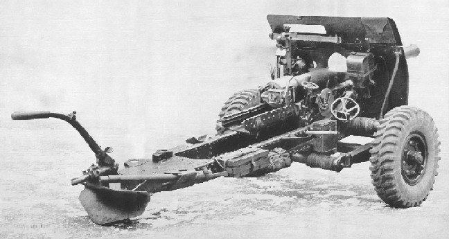
After several designs it was decided to adopt a 3.45 inch (87mm) gun-howitzer, using three propelling charges and this was approved in 1935. At first the new guns were provided by removing the barrels of the 18-pdrs from their carriages and insert the new 25-pdr barrel and breech. This led to them being initially known as "18/25-pdrs", although the official name was the "Ordnance 3.45-in". In 1938 popular sentiment led to the gun being called the "25-pdr".
A new carriage to better suit the heavier gun was designed to replace the temporary 18/25-pdr conversion (shown left) and this had a slit-trial. However, after tests in 1938 the users preferred a box-trail type of firing platform, as this allowed the gun to be rapidly traversed in any direction. This pattern was put into production in late 1939. This led to the campaign in France being fought with the 18/25-pdr, though a few of the new 25-pdr equipment did see some action in Norway.
18/25-pdr, Data:
|
Calibre (mm/in) |
Shell Weight (Kg/lb.) |
Max Velocity (m/sec / ft/sec) |
Max range (m/yards) |
Weight in action (Kg/lb.) |
Elevation (degrees) |
Traverse (degrees left and right) |
|
87/3.45 |
11.3/25 |
442/1450 |
11,700/12,800 |
1625/3584 |
-5/+37.5 |
4 |
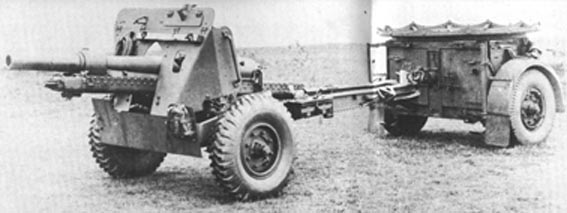
The 25-pdr was one of the best field guns of its day, although it did not fire as heavier shell as the German and American 105mm (4.1-in) weapons, it was easier to handle in action and has an excellent range. It was provided with an excellent anti-tank shot, which proved to be of immense use in the Western Desert, when the 2-pdr anti-tank gun was outmatched by the German armour. This was also proved at Villers-Bocage, when 5 RHA, firing over open sights, accounted for a number of the German tanks and other armour destroyed in the battle of the "Brigade Box".
Click here to see a detailed picture of the various parts of the gun.
In order to extract the best performance, a muzzle brake was fitted in 1942 and an extra propelling charge was used to provide a higher muzzle velocity with 20 pound AP shot. The gun was capable of firing a wide range of ammunition, including white and coloured smoke, flare, incendiary, propaganda and squash-head shells, as well the normal HE, Shrapnel and AP shots.
The gun remained in front line service until the late 1960's and was still used in reserve until the early 1970's.
The basic gun was also adapted for use in several self-propelled guns, such as the Bishop and Sexton
25-pdr, Data:
|
Calibre (mm/in) |
Shell Weight (Kg/lb.) |
Max Velocity (m/sec / ft/sec) |
Max range (m/yards) |
Weight in action (Kg/lb.) |
Elevation (degrees) |
Traverse (degrees left and right) |
1st Line Ammo (per gun |
|
87/3.45 |
11.3/25 |
518/1700 |
12,250/13,400 |
1800/3984 |
-5/+40 |
4 |
114 HE 16 Smoke 12 AP |
| 20 pound Anti-Tank Shot, performance |
Max Velocity (m/sec / ft/sec) |
Max range (m/yards) |
| MK 1 and MK 2 guns (Charge 3) |
518/1550 |
1,828/2000 |
| MK 2 guns (Super Charge) | 564/1850 | 2743/3000 |
| MK 2 gun with muzzle brake (Super Charge + No.1 Supplementary Charge) | 609/2000 | 2743/3000 |
| 25 pdr Field Gun | |
In 1942 a number of British artillery units in the Middle East were equipped with the American Priest 105mm (4.13-in) self-propelled Howitzers. While this was an excellent weapon, the 105mm round was not a standard British calibre and thus required special supply arrangements. It was obvious that if the Priest could be fitted with a 25-pdr gun, supply would be much easier. Although the Americans happy to produce a prototype they were not prepared to devote resource for their war effort, for something which they would not use, as they were not intending to adopt the 25-pdr as a standard US weapon. Thus the British requested that a similar design be built in Canada, using the chassis of the RAM tank then in production, which did in fact use components of the US M3 medium tank.
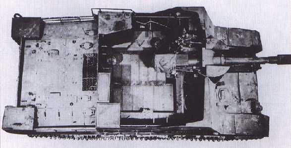
The Sexton was a relatively simple design with an open-topped superstructure, mounted on the running gear of the RAM. In the front plate, the 25-pdr was fitted so as to allow full elevation and a traverse of 25 degrees left and 15 degrees right. The recoil system was adjusted and locked to give a constant recoil length of 20-in (508mm). The driver and 5 man gun crew all rode in the fighting equipment and 112 cartridges and an equivalent number of HE, Smoke and AP shells could be carried.
The first 124 vehicles produced were designated Sexton I and can be distinguished by the tapering rear deck. The later Sexton II has a vertical box at each rear corner, one of, which contained the vehicle batteries and the other an auxiliary generator for charging them. A canvas cover, for the fighting compartment, was provided to protect the crew from bad weather.
A total of 2510 vehicles were produced and the Sexton served in the British Army from 1943 through to 1956. A small number of Sexton Command Post tanks were also built, which used the same hull, but without a gun, so that additional radios and fire-control equipment could be carried. The picture below shows the inside of a Sexton II.
The Sexton and its 25 pdr Howitzer proved to be an adaptable weapon as shown by its innovative use by CC Battery, 5 RHA on at least two occasions. The first use was as a heavy mortar, when in France a large concentration of infantry was spotted on the other site of a hill, the guns were elevated to almost maximum and the firing charge (the lowest power one available) was used to propel the shells over the hill like a mortar. Another use was for hit and run long range sniping, when in Holland, the Battery crept forward at night, into 'no mans land' and then used the 'Supercharge' facility to shell a German ammunition dump which could not be reached from British lines. After a few rounds had been fired the Battery about turned and headed back to the British lines before any counter battery fire from the Germans could fall, with the mission a success. One final use was marking dug in German tanks for Typhoon fighter-bombers to knock out with their rockets. This involved ranging each gun onto the tanks with HE (which would of course not do any damage itself), but once this had been achieved when the Typhoons were ready, coloured smoke was used to mark each tank so the RAF could see them and duly attack them.
Specification:-
|
Armament: |
25-pdr C MK II, with 112 rounds on board, plus 2 x 0.303 Bren Machine Guns |
|
Crew: |
6, including driver |
|
Speed: |
24 mph (39 km/h) |
|
Armour thickness: |
4.25-0.5 in (104-12.7mm) |
|
Weight: |
25.86 tonnes |
|
Length: |
20 ft 1 in (6.12m) |
|
Width: |
8 ft 11in (2.72m) |
|
Height: |
6 ft 11 in (2.11m) |
|
Powerplant: |
Continental 9-cylinder radial gasoline engine, producing 460 bhp @ 2400 rpm |
|
Range: |
125 miles (200 Km) |
| Sexton 25 pdr Self-Propelled Gun |
Shot and Shell - Howitzer and Gun:
The main difference between guns and howitzers, it that guns fire 'directly' at their targets, while howitzers fire 'indirectly' at high angles, dropping their shells on to targets hidden by hills or fortifications. The plunging fire of a howitzer is also ideal for cracking open heavy gun emplacements and defences. Howitzers usually fire at shorter range that guns, which means that the propellant charges of howitzer shells are comparatively small. This in turn means that howitzers have shorter barrels than guns.
The basic distinction was narrowed by 1939 with the appearance of the multi-purpose gun howitzer, in the shape of the British 25-pdr (above). The chart shows the comparative ranges of guns and howitzers, of various calibres. Please note the longer range of the gun.
Anti-tank Ordnance
2 Pounder Anti-tank Gun: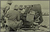
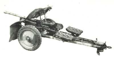
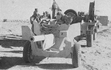
Originally developed in the mid 1930's to combat the tanks of that era, the 2-pdr (like most of its contemporaries) was of 40mm (1.57 in) calibre. However, it was more elegantly engineered than the other designs, with an ingenious three-legged carriage which allowed the travelling wheels to be lifted clear of the ground so that the gun could easily traverse through 360 degrees. The traversing gear was a two-speed system, giving fast movement for target acquisition and the slow movement for precise aiming. A shield was fitted to protect the gunners, which also carried a ready-use locker of ammunition. All this complication meant that production was slow, so in late 1938 the army purchased a number of French 25mm Mle Hotchkiss anti-tank guns as a stop gap measure.
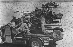
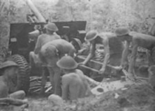
Originally anti-tank shooting was considered an infantry task, but as it became clear that the infantry had more than enough to do the Royal Artillery took over this role in 1938. The 2-pdr did not perform well against some of the heavier German tanks and was easily outclassed in the desert, but they did prove effective in the Far East against the more lightly armoured Japanese tanks. One measure to make the 2-pdr more mobile, in North Africa, was to mount it en-portee on the rear of lorries, but this did make it more susceptible to small arms fire which could easily knock out the carrier. The picture (left) shows a number of 2-pdr guns portee, which could either be unloaded for action, or more commonly fired from the back of the lorry.
2-pdr, Data:
|
Calibre (mm/in) |
Shot type |
Shell Weight (Kg/lb.) |
Muzzle Velocity (m/sec / ft/sec) |
Max range (m/yards) |
Weight in action (Kg/lb.) |
Penetration |
|
40/1.57 |
AP |
0.91/2 |
807/2650 |
7315/8000 |
769/1757 |
42mm @1000m |
Notes: AP = Armour Piecing Shot. Penetration figures are given at 30 degrees angle of impact against homogeneous plate
| 2 pdr Anti-Tank Gun |
37mm Bofors (M1936) Anti-tank Gun:
Although development of a replacement for the 6-pdr was in hand before the start of the war, the main Anti-Tank gun of the British Army was the 2-pdr, especially within the BEF in France, 1940. However, shortly before the start of the war the Sudanese Government bought a number of 37mm Anti-Tank guns from AB Bofors of Sweden and when war broke out, these were made available to the British Army in the Western Desert to make up for their lack of 2-pdrs. They known as Ordnance Q.F. 37 mm Mk 1 and were used mainly by 3rd RHA and 106th RHA (Lancashire Hussars) within 7th Armoured Division, although some did also see use in Somaliland, against the Italians there.
 The
performance was not significantly less than that of the 2-pdr and it was often
carried "portee" on the back of a vehicle, although a separate limber
was provided and had a crew of 5. It proved very useful in the early stages of
the desert war, until sufficient 2-pdr guns were available, but as with the
2-pdr its effective use was shorted by the increased armour of German Tanks. In
contrast to the 2-pdr it could also fire HE and Incendiary (filled with White
phosphorus) rounds, too.
The
performance was not significantly less than that of the 2-pdr and it was often
carried "portee" on the back of a vehicle, although a separate limber
was provided and had a crew of 5. It proved very useful in the early stages of
the desert war, until sufficient 2-pdr guns were available, but as with the
2-pdr its effective use was shorted by the increased armour of German Tanks. In
contrast to the 2-pdr it could also fire HE and Incendiary (filled with White
phosphorus) rounds, too.
37mm Bofors (Model 1936), Data:
|
Calibre (mm/in) |
Shot type |
Shell Weight (Kg/lb.) |
Muzzle Velocity (m/sec / ft/sec) |
Max range (m/yards) |
Weight in action (Kg/lb.) |
Penetration |
|
37/1.45 |
AP/HE |
0.7/1.53 |
800/2625 |
7100/7765 |
335/738 |
40mm @1000m |
Notes: A
P/HE = Armour Piecing Shell. Penetration figures are given at 30 degrees angle of impact against homogeneous plate| 37mm Bofors Anti-Tank Gun |
6 Pounder Anti-tank Gun:
Woolwich Arsenal appreciated that the 2-pdr would soon be out of date and in 1938 began designing a 57mm (2.24 inch) 6-pdr replacement, albeit with a low priority. A pilot was built and test fired in 1939, but the design was then shelved until such as time as it may be needed. Following the Fall of France with the loss of several hundred 2-pdr guns after the fall of France, the British Army was severely short of anti-tank weapons. So along with this and the poor performance of the 2-pdr, a replacement in the shape of the 6-pdr was proposed. However, to get the 6-pdr into production would have absorbed all the facilities then involved with producing the 2-pdr, but as in the summer of 1940 a gun in the hand was worth any number in the pipeline. This along with the fact that the troops were familiar with the 2-pdr (and would need re-training on the new 6-pdr) meant that 2-pdr stayed in production at the expense of the 6-pdr.
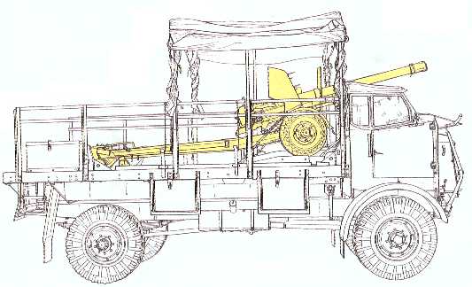
A contract was placed for 400 guns in June 1940, but it was not until the demand for the 2-pdr was satisfied, that the first 6-pdr guns appeared in November 1941. By this time the 2-pdr was well outclassed by the German armour which was armed with a heavier 50mm or 75mm guns and thus could stand off, out of range of the 2-pdr and shell the anti-tank guns into submission. With these tactics it took skill and courage to successful engage a German tank with a 2-pdr. The issue of the 6-pdr changed all this and opened up the battle, along with allowing many 25-pdr field guns to be returned to their primary task of infantry support instead of being used as anti-tank weapons. An example of a 6-pdr Portee is shown in the below sketch.
6-pdr, Data:
|
Calibre (mm/in) |
Shot type (see notes) |
Shell Weight (Kg/lb.) |
Muzzle Velocity (m/sec / ft/sec) |
Max range (m/yards) |
Weight in action (Kg/lb.) |
Penetration |
|
57/2.24 |
HE AP APCBC APCR APDS |
2.7/6 2.7/6 3.2/7 1.8/4 1.5/3.2 |
823/2700 821/2693 846/2775 1075/3528 1234/4050 |
5030/5500 |
1597/3521 |
- 74mm @ 1000m 88mm @ 1000m 90mm @ 1000m 146mm @ 1000m |
Notes: AP = Armour Piecing Shot, APCBC = Capped, ballistic capped, shot, APCR = Composite rigid (Tungsten corded) Shot, APDS = Discarding sabot shot. Penetration figures are given at 30 degrees angle of impact against homogeneous plate
| 6 pdr Anti-Tank Gun |
17 Pounder Anti-tank Gun:
By 1942, the 6-pdr was starting to become obsolete as the newer German tanks became even more heavily armoured, but back in 1940 the subject of an eventually replacement for the 6-pdr had been raised. What was proposed was a 3-in (76mm) weapon firing a 17-lb shot. By early 1942 prototypes had been build, tested and approved and by May 1942 the 17-pdr gun had been formally introduced. This was a considerable leap forward and the 17-pdr was to become one of the most formidable anti-tank guns of the war.
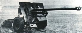
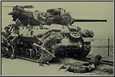
As the first guns were being produced news of the appearance of the German Tiger Tank, so about 100 17-pdr barrels were fitted to 25-pdr carriages, as the proper 17-pdr split-trail carriages were not ready, and flown to North Africa, in 1943, to counter this new threat. The guns were code named "Pheasant" (officially known as 17-pdr MK2) and proved remarkably stable and robust in use, shown left. They served until the correct mounts were available. It should be noted that although these guns were rushed to North Africa to combat the Tiger tank, it was in fact a 6-pdr, which claimed the first Tiger "kill". The gun went on to be mounted in the Sherman "Firefly", the Challenger Tank and the Achilles and Archer Tank Destroyers.
17-pdr, Data:
|
Calibre (mm/in) |
Shot type (see notes) |
Shell Weight (Kg/lb.) |
Muzzle Velocity (m/sec / ft/sec) |
Max range (m/yards) |
Weight in action (Kg/lb.) |
Penetration |
|
76/3 |
HE AP APC APDS |
7/15.4 7.7/16.9 7.7/16.9 3.5/7.8 |
846/2775 883/2900 883/2900 1204/2900 |
9150/10,000 |
2097/4624 |
- 109mm @ 1000m 188mm @ 1000m 231mm @ 1000m |
Notes: AP = Armour Piecing, APC = Capped shot, APDS = Discarding sabot shot. Penetration figures are given at 30 degrees angle of impact against homogeneous plate
| 17 pdr Anti-Tank Gun (Top video also shows 17/25 pdr 'Pheasant' Anti-Tank gun) |
Wolverine and Achilles Tank Destroyer:
Although these guns were built onto tank chassis and looked very much like tanks, they were crewed by the Royal Artillery.
The Wolverine Tank Destroyer was actually the US M10 Tank Destroyer, fitted with the US 76mm anti-tank gun, supplied to the British under the lend-lease agreement, whereas the Achilles was a version of the M10 fitted with the British 17-pdr anti-tank gun, in a modified turret.
The basic M10 was development of the US M4 Sherman, but with modified shape and thinner armour, but it suffered no real loss of protection, due to the slopped armour, plus the speed was slightly increased, too. It was useful for engaging the heavier German tanks and was primarily used, like most tank destroyers, in ambush rather than direct advance. Like most similar vehicles it had an open topped turret, which meant the crew were susceptible to air-burst artillery. The picture below, of a Wolverine, shows the general configuration of both types of vehicle, but the Achilles (17-pdr) would have been fitted with a muzzle break and counterweight on the barrel. It is also interesting to note that in the War Diaries of 260th Anti-Tank Battery, from 65th Anti-Tank Regt (Norfolk Yeomanry) that the 17-pdr version is also referred to as a 'Mayfly' on in their case 'Mayflies' having received four of then on 16th May 1944.
It was the norm that in armoured division, and Corps, anti-tank regiments the two senior batteries were equipped with these Tank Destroyers, while the other batteries were equipped with 17-pdr guns.
Specification:
|
Armament: |
Wolverine (M10): 1 x 3-in (76mm), plus 1 x 0.303 Bren gun. Achilles: 1 x 17-pdr, plus 1 x 0.303 Bren gun. |
|
Armour: |
57mm (2.26 in) max |
|
Weight: |
29.6 Tonnes |
| M10 Achilles and Wolverine Tank Destroyers. | |
| M10 Achilles (17 pdr) Tank Destroyer. Markings are for 65th Anti-Tank Regt (Norfolk Yeomanry) RA. Most likely 260th Battery | M10 Achilles (17 pdr) Tank Destroyer. Markings are for 75th Anti-Tank Regt RA |
| M10 Wolverine (US 76mm) Tank Destroyer | US Film on the M10 |
Anti-tank Ammunition:
Consideration must be given to the ammunition used by the British Anti-tank guns, when reviewing their performance. The basic armour-piecing (AP) shot was a solid steel projectile with a hard point, which would simple smash through armour and do damage to the inside of the tanks and its crew, resulting from the splinters and fragments knocked of from the impact. AP shot was satisfactory against homogeneous armour, but tended to shatter when it struck face-hardened armour. To counter this armour-piecing capped (APC) shot was developed, which had a penetrating cap over the point to counter. Since the cap was now blunt a light steel cap of more pointed form was placed on it as a wind shield, leading to APCBC (armour-piecing capped, ballistic cap) shot, the ultimate solid shot design.
To deal with harder and thicker armour, tungsten carbide was adopted as the penetrating material. Since it was heavier than steel, it was not possible to make a simple shot, so a core of tungsten was surrounded by a steel an light alloy body to make APCR shot (armour-piecing composite rigid). While this had a high velocity and good armour piecing power at short and medium ranges, its velocity fell off rapidly in flight until at longer ranges. This mean it was dropped in favour of APDS (armour-piecing discarding sabot) in which the alloy sheath was stripped away as the shot left the muzzle and the tungsten core flew to the target flew to the target at high velocity. This was introduced for the 6-pdr and 17-pdr in 1944 and the APDS shot the 17-pdr became the most powerful tank killer in Europe in 1944-45.
Anti-Aircraft Ordnance
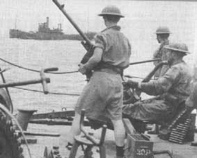
This gun was designed by the BOFORS company in Sweden, and was used by many armies around the world, which was developed during the 1930's and eventually built under licence by the British. It was a 40mm (1.57-in) lightweight weapon on a four wheeled carriage, which was capable of being towed at high speed and could be fired from it’s wheels. Normally there would be a crew of six: Elevation Trainer & firer (on the left - when viewed from the breech looking down the barrel), Azimuth Trainer (on the right), 2 x Breech Loaders (who stood on the gun platform to re-load), 2 x Loaders who fed the Breech Loaders with spare Ammo clips, due to its high rate of fire. There would also be a Gun commander, who would also 'spot' for the targets, although the Bofors Gun could accept targeting information from a separate 'predictor' system. It was a widely used weapon, serving as a extremely effect ant-aircraft gun, occasionally as an anti-tank gun and during night attacks it was used fire tracer as a guideline for infantry negotiating cleared paths in minefields. Some variants were also fitted with a shield.
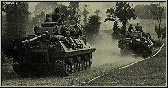
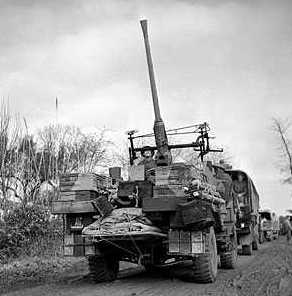 From 1944 a lorry-mounted
version (shown left) was deployed especially within armoured divisions, to allow mobile
anti-aircraft support. This normally took the form of 18 guns (three troops of
six) per light anti-aircraft regiment.
From 1944 a lorry-mounted
version (shown left) was deployed especially within armoured divisions, to allow mobile
anti-aircraft support. This normally took the form of 18 guns (three troops of
six) per light anti-aircraft regiment.
40mm, BOFORS, Data:
|
Calibre (mm/in) |
Rate of fire (rpm) |
Shell Weight (Kg/lb.) |
Effective Altitude (m/feet) |
Weight in action |
Crew |
|
40/1.57 |
120 |
0.91/2 |
3,658/12,000 |
2.4 tonnes |
6 (average) |
| 40mm Bofors Anti-Aircraft Gun |
20mm Breda AA/AT Gun (Captured Italian Weapon):
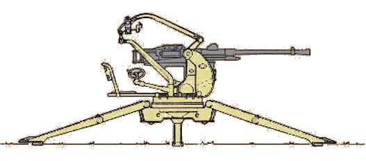
It may seem strange to be writing about an Italian weapon on a page about those used by British troops, but in North Africa many captured weapons (including tanks) were regularly used against their original owners by either side. This is the case with the 20mm Breda AA/AT gun, which saw service with LAA/Anti-Tank Regiments in the earlier years of the desert war.
This gun was of the two standard Italian 20mm anti-aircraft guns and was the Cannone-Mitragliera da 20/65 modello 35 (Breda) which was first manufactured in 1934. It was designed as a dual purpose weapon for use against ground and air targets and was taken into service by the Italian army in 1935. The 20mm Breda was a very effective weapon and was much used by the Italian Army. It had a rather complicated twin-wheeled carriage that could be towed into action behind a truck but that was light enough to be broken down into four pack loads for man or mule carriage.
 In action the gun required a three-man crew. The aimer sat on
the gun and used a complex telescopic sight incorporating a predictor function.
Ammunition was fed into the gun on 12-round trays and the feed mechanism
contained the feature of placing the spent cartridges back into the tray once it
was fired. This feature appeared on many Italian automatic weapons and had the
advantage of keeping the gun position tidy.
In action the gun required a three-man crew. The aimer sat on
the gun and used a complex telescopic sight incorporating a predictor function.
Ammunition was fed into the gun on 12-round trays and the feed mechanism
contained the feature of placing the spent cartridges back into the tray once it
was fired. This feature appeared on many Italian automatic weapons and had the
advantage of keeping the gun position tidy.
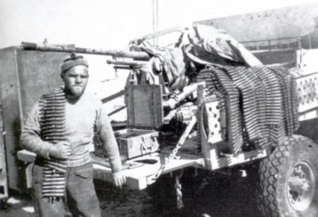 Against
ground targets the gun fired armour-piercing rounds, while aircraft targets were
engaged with a high explosive projectile that incorporated a very sensitive
percussion fuse to operate against light aircraft structures. The latter
projectile also had a self-destruct feature if it did not hit a target. The
tripod platform of the gun provided a steady base for firing and against
aircraft the gun proved very successful. Against tanks it was less effective,
but any weapons captured by the Allies during the North African campaigns were
usually mounted on the light armoured cars to provide them with more offensive
capability than a machine gun provided and Portee to provide mobile air defence
for armoured columns. The Long Range Desert Group also mounted them on the rear
of some it is vehicles nicknaming them 'Scorpions' as they then had a sting
in their tail.
Against
ground targets the gun fired armour-piercing rounds, while aircraft targets were
engaged with a high explosive projectile that incorporated a very sensitive
percussion fuse to operate against light aircraft structures. The latter
projectile also had a self-destruct feature if it did not hit a target. The
tripod platform of the gun provided a steady base for firing and against
aircraft the gun proved very successful. Against tanks it was less effective,
but any weapons captured by the Allies during the North African campaigns were
usually mounted on the light armoured cars to provide them with more offensive
capability than a machine gun provided and Portee to provide mobile air defence
for armoured columns. The Long Range Desert Group also mounted them on the rear
of some it is vehicles nicknaming them 'Scorpions' as they then had a sting
in their tail.
The Germans also took over numbers of Breda guns for their own use in North Africa under the designation 2-cm Breda (i) and they also even used them when a number of Panzer MKII's were refitted as reconnaissance vehicles. When used for the latter it fired from a loose belt or hundred round belts stored in canister. Breda guns were also given to the German allies after Italy’s surrender, such as Slovakia, and was used in China as well. There was also a modello 39 that was a more complex weapon on a static pedestal type mounting on which the gun itself was suspended below curved arms that carried the sighting system. This version was usually retained for homeland defence of Italy.
20mm, Breda AA/AT, Data:
|
Calibre (mm/in) |
Rate of fire (rpm) |
Shell Weight (Kg/lb.) |
Length (m/in) |
Effective Altitude (m/feet) |
Weight in action (Kg/lb.) |
Elevation |
Crew |
|
20/0.78 |
200-220 cyclic |
0.135/.298 |
1.3/51.2 |
2,500/8,202 |
307.35/678 |
–10º to +80º |
3 |
| 20mm Breda AA/AT Gun |
M16 Quad 0.5 Calibre AA Half-Track (Multiple Gun Carriage):
This was a development of the normal M3 or M5 Half track converted to carry a powered quadruple 0.5" Browning Machine Gun mounted in a Maxson turret on a M45 Mount.
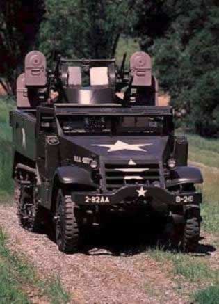
The gun mount could traverse at 60° per second and fire 400-500 rounds per minute, with a range of 7,200 yards. The system was fitted with 'Interrupter switches' that prevented guns from firing when entering drivers compartment area. The gunner would sit on a seat reclined at 45° with the sight positioned so that the he could follow the sight without having to move. The control grips were on a handlebar that were located on a post between his knees and by rotating the handlebar would rotate the gun or raise and lower it. The two sides would fold down when in use and two cargo boxes at the rear.
This was mainly used by the US Army in the Northern Europe, but towards the end of the war British Light Anti-aircraft Regiments were issued with some, as was 15th LAA (Isle of Man) Regiment.
M16 Quad 0.5 Calibre AA, Data:
|
Calibre (mm/in) |
Rate of fire (rpm) |
Traverse |
Elevation |
Weight in action |
Speed (Km/h/Mph) |
Crew |
|
12.7/0.5 x 4 |
400-500 x 4 |
360° at 60° per second |
-10° to +90° |
9.8 tonnes |
72/45 |
4 (Commander, driver, gunner, 2 loaders) |
Other than the above the specification for the vehicle is as per the standard infantry half-track and the machine gun as per the data on the normal 0.5" Browning Machine Gun
| Quad 0.5" Mount as used on the M16 Halftrack |
Counter Bombardment and Counter Mortar Battery Equipment
During World War One most armies tried 'aural' methods, basically large ear trumpets, to try and locate the position of enemy Mortars and Artillery. However, the British and French soon abandoned this approach in favour of using microphone methods.
To be successful microphone sound ranging needed two technologies, the first of which was a way to detect the low frequency sound (about 20 hertz) of guns firing, the second a way of recording the signals. The former was achieved by the invention of the low frequency microphone using a heated platinum filament; with the second being provided by a pen recorder, in which the 'pens' plotted a trace-line on electrical on sensitive paper or 'film'.
Sound ranging utilised a system were several microphones, deployed in standard pattern, connected to a pen recorder in a plotting centre. Typically this pattern (or Base) consisted of up to 6 microphones, was about 3000 to 5000 metres behind the front line and ideally well behind as many friendly field artillery positions as possible. The best pattern from a plotting perspective was one in which the microphones were equidistant as it was simplest. This type of pattern could be either straight line or curved and in it each microphone was paired with its neighbours and each pair was a 'sub-base'
When deployed in a straight line pattern the distance between the two outer microphones would be up to about 8,000 metres, while in a curved pattern this could be as short as an arc of about 1500 metres at a 16,000m radius. The problem was fitting the pattern to the terrain, so that the microphones were in good listening positions. This was important as the actual terrain could have many undesirable effects that interfered with results. When as a regular pattern was not possible then an irregular one could be used as long as the position of each microphone was actually known for the calculations. It could take between 6 to 12 hours to deploy and survey a pattern of 6 microphones.
This recorded the relative times of arrival at each microphone of the sound of guns firing. There were three basic ways of using this system, but all used the time difference of the detected sounds received by each detector to predict the location of the enemy mortar or gun. These were based upon the fact that a firing gun produces three different sets of sound waves at different frequencies:
The last was the most practical as it could be used to range friendly fire onto a enemies firing location, as the pen recorder film recorded the duration of the sound (to 1/100 second) and the strength of its pressure wave. By using the relative time difference between the microphones to deduce location from the sound of the gun-wave. As a bonus the recorded sound shape of a gun-wave on the film was often distinctive for each calibre of gun.
By comparing the recordings of the gun-wave and the burst-wave allowed the time of flight to be determined and graphs were used to find the calibre by this means as well. The problem with sound ranging was that lots of guns firing together were liable to 'swamp' the recording. Also it was not practical to have the pen-recorder running continuously, therefore an Advance Post (AP) at least 1000 metres in front of the microphones was required so that it could switch on the microphones and recorders when the enemy were firing.
The sound waves are affected by wind and temperature, basically as the speed of sound varies with the air temperature, and so it was necessary to correct the data recorded on the film in the plotting centre, before it could be used. This lead to the requirement for a need for a detachment of RAF meteorologists to provide the meteorological data, being assigned to Counter Bombardment and Counter Mortar Batteries.
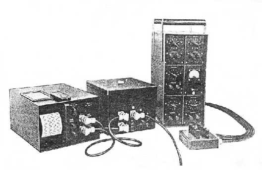
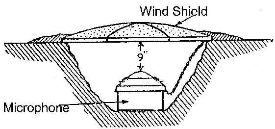
It was discovered that the normal 6-pen equipment was that it was not sensitive enough to detect and locate 81mm mortars, so by the second half of 1944 the 4-pen recorder (Recorder SR No 2 Mk 1) was introduced. The picture (below left) shows, (from the left to right) the recorder, power supply and amplifier. The 4 microphones (below right) for this system were placed in shallow pits, covered with windshields, typically 400 to 1000 yards apart and connected back to the controller by dedicated cables.
|
|
 |
In 1943 the British started mortar locating experiments with radars and in 1944 their use became quite extensive in both NW Europe and Italy. The radars used were AA No 3, Mk 2 (GL III) and AA No 3, Mk 5 (SCR 584). The latter were better and could produce locations accurate to about 25 yards. By the end of the war the Radars designed for observing artillery fire, ground surveillance and mortar locating were becoming very advanced in their designs and their successors are still in use today. By the middle of 1944 British and Canadian army radar batteries were formed in NW Europe, and were primarily used in a counter-mortar role.
An experimental set, Model A, had been completed and tested by British Thompson Houston (BTH) at Rugby in April 1941.
After trials in May and June at A.D.R.D.E. Christchurch, an improved and modified set, Model B, was introduced in July and an order was placed for 28 hand-built pre-production models, and a full production order for 900 sets was also placed in
July 1941. Five hand-built prototypes were built between December 1941 and April 1942, and only 8 in total by the end of 1942. Production increased through 1943 with 548 sets manufactured during 1944. Production ceased in April 1945 with a total of 876 sets delivered, 50
of which were sent to the USSR. Unfortunately due to production and design difficulties, by the time the No3 Mk2 reached full production it was already obsolete. The introduction in 1944 of the US built SCR584 with auto-tracking made this highly sought after radar set the
radar of choice. However the No3 Mk2 continued in use with the services for many years after the war with many being converted for weather observation. In the early 1950's the No3 Mk2 was deployed in Germany with
Independent Locating Batteries and considering its age it performed very well against the 3" and 4.2" mortars used in training.
They continued to be used until 1957 or 1958, with some being taken over by the
UK Meteorological Office in the mid 1950's and used until the early 1960's.
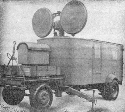 The AA No 3, Mk 2 Radar was developed
from earlier AA No. 3 Mk. 3 and was a Trailer mounted system, weighing 9.5tons.
It had four operators and used a separate trailer mounted 15 KVA generator for
power. It operated at a frequency of 3 GHz (10-cm wavelength), with a maximum
range 8,000 yards for detecting medium (81mm) mortar. It had a prediction
accuracy of ± 25 yards when used with Plotter 3-pen FA No. 1, or 100-150 yards
when used without plotter. The version used Divisional Counter Mortar batteries
was the No3 MK2(F) and in its unmodified form was the only radar used for mortar location during the
war.
The AA No 3, Mk 2 Radar was developed
from earlier AA No. 3 Mk. 3 and was a Trailer mounted system, weighing 9.5tons.
It had four operators and used a separate trailer mounted 15 KVA generator for
power. It operated at a frequency of 3 GHz (10-cm wavelength), with a maximum
range 8,000 yards for detecting medium (81mm) mortar. It had a prediction
accuracy of ± 25 yards when used with Plotter 3-pen FA No. 1, or 100-150 yards
when used without plotter. The version used Divisional Counter Mortar batteries
was the No3 MK2(F) and in its unmodified form was the only radar used for mortar location during the
war.
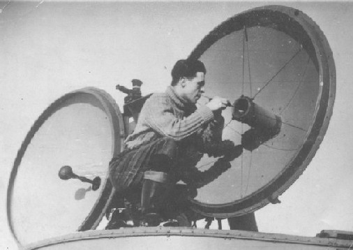
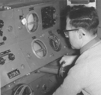
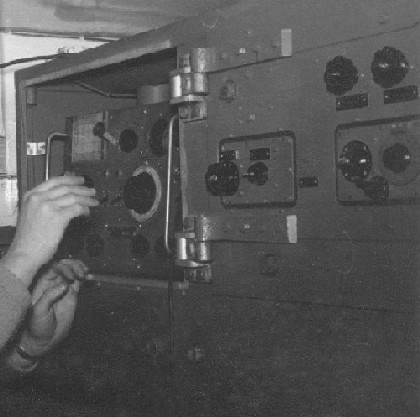
The pictures below show the aerials and some of the items inside the cabin and date from its use by the Meteorological Office (1955), though there were no major modifications to the system.
|
|
|
|
| Related Websites |
| Anti Aircraft Radar No3 Mk2 |
| Radar No3 Mk2 Restoration |
Transport
Apart from the many lorries used by the British Army throughout the war, there was three key vehicles used by the artillery as a gun and limber tractor. These were the Quad Field Gun Tractor, Morris CDSW LAA Tractor and the Universal Carrier.
This vehicle was used throughout the war to tow the 18-pdr, 25-pdr and 17-pdr Ordnance, the gun crew and early in the war the gun limber too. Over 28,000 of these vehicles were built. The picture to the right shows a typical configuration of a Quad Tractor, limber and 25-pdr gun.
| Quad Artillery Tractor |
These vehicles were mainly used for towing the 6-pdr Anti-tank gun. To see details of this weapon please visit the
Universal Carrier details on the Infantry page.:
The first CDSW was made in 1935 being specifically designed to tow a field gun hence the large tow hook at rear. In those days the gun would have been an
18 pdr or a 4.5 Howitzer. Both these were soon to be superseded by the 25 pdr gun which gave such excellent service in WWII. In about 1938 came the Light AA version to tow the Bofors gun.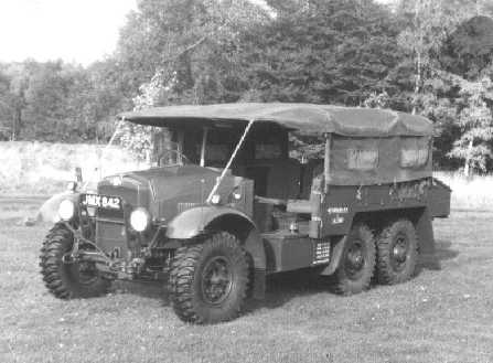
Production of these latter two types continued after the war started and with one production run in 1940 producing 980 Bofors CDSW along and 60
Light Breakdown CDSW, variants. Although the Field Artillery Tractor version of the CDSW had been superseded in 1939 by the QUAD 4 x 4 (above), a considerable number of CDSW went out with the BEF to France in September, 1939, with a great number of them being lost at Dunkirk.
Divisional Equipment Page Tanks Page Armoured Cars Page Infantry Page Other Equipment Page